
12v Input 160w Output Plugin DC-DC ATX Power Supply
- Small, Silent and Smart PSU [S3PSU]
- Operates at only 12v Input
- High Efficiency [>94%]
- Arm® Cortex®-M0+ 32-bit RISC MCU Inside
- Highly Reliable Tantalum Capacitors
- OCP, OVP, and OTP
- Direct plugin to Motherboard, Cutting out ATX cable
- Compact Board Size: 56mm (L) x 34mm (W) x 16mm (H)


DC INPUT
You can choose AC power adatper with 12VDC output and 5.5mm x 2.5mm size pin as the power source.
| Input Channel | DC Input Voltage | DC Jack | DC Input Cable Length |
|---|---|---|---|
| 1 | 12V (OVP at 13~13.5V) | 5.5mm x 2.5mm | 350mm |
POWER RATINGS
The power rating for each output rail is shown in the following table. Maximum 8A continous current is guaranteed in the 12V output rail. Forced air ventilation is required for operating at max load. For fanless or improper ventilation operation derate the output of the 12V rail until PSU temperature falls below 65℃. Peak load should not exceed 60 seconds. Combined max power output should not exceed more than 120 Watts.
| Voltage Rail | Max Load (A) | Peak Load (A) | Regulation |
|---|---|---|---|
| +12V | 8 | 12 | Switched Input |
| +5V | 6 | 8 | ±1.5% |
| +5VSB | 1.5 | 2 | ±1.5% |
| +3.3V | 6 | 8 | ±1.5% |
| -12V | 0.05 | 0.1 | ±5% |
PROTECTION
OCP, OVP, short circuit and no load operation.
Overload Protection
The power supply will be shutdown and latch off when load power over 110% ~ 160% of the rated DC output.
Over Current Protection
The power supply shall have current limit to prevent the +12V, +5V and +3.3V outputs from exceeding the values shown in the following table. If the current limits are exceeded the power supply shall shutdown and latch off.
| Output Rail | Over Current Limit |
|---|---|
| +12V | Switched Input |
| +5V | 8~10A |
| +3.3V | 8~10A |
Over Voltage Protection
The microcontroller in the PSU monitors all output rails and provides over voltage protection as defined in the following table.
| Output Rail | Minimum (V) | Normal (V) | Maximum (V) |
|---|---|---|---|
| +12V | 13.4 | 15 | 15.6 |
| +5V | 5.74 | 6.3 | 7 |
| +3.3V | 3.76 | 4.2 | 4.3 |
Short Circuit Protection
An output short circuit is defined as any output impedance of less than 0.1 ohms. The power supply shall shut down and latch off for shorting the +3.3V, +5V, or +12V rails to return or any other rail.
No Load Operation
No damage or hazardous condition should occur with all the DC output connectors disconnected from the load. The PSU may latch.
I/O PIN DIAGRAM
The on-board 24pin connector is the standard ATX power connector which can directly plugin to the 24pin ATX power connector on the motherboard. The on-board 5pin is used by the cable set to generate voltages on EPS 12V, SATA and peripheral connectors.

TIMING
Compliance with Intel ATX specification version 2.01. Remote ON/OFF control is as follows.
- When the logic level “PS-ON” is low, the DC outputs are to be enabled.
- When the logic level is high or open collector, the DC outputs are to be disabled.

- T1: Power-on time. The time from when PSON# is pulled low to when the +12V, +5V and +3.3V outputs are within the regulation ranges. The power-on time shall be less than 500ms (T1 < 500ms)
- T2: Rise time. The output voltages shall rise from ≤10% of nominal to within the regulation ranges within 0.1 ms to 20 ms (0.1 ≤ T2 ≤ 20ms)
- T3: Power good signal turn on delay time (100 < T3 < 500ms)
- T4: Power good signal rise time (T4 ≤ 10ms)
- T5: Voltage input loss to PGOOD hold-up time (T5 ≥ 16ms)
- T6: Power down warning (T6 ≥ 1ms)
CABLE DIAGRAM
Definition of the wire harness.
Cable Set
This output cable set is connected to the PSU via the EH 5pin connector.

DC Input Cable
The input cable has been soldered to the power supply. The DC receptacle with panel mount has Pin size of 5.5mm x 2.5mm. Internal is positive and external is negative.


Connectors
The wire length and number of connectors of the cable set are summarized in the following table.
| Main Power 24P | EPS 12V 4+4P | PCIE 6+2P | SATA | Peripheral 4P | CPU FAN 4P | |
|---|---|---|---|---|---|---|
| Outlook | 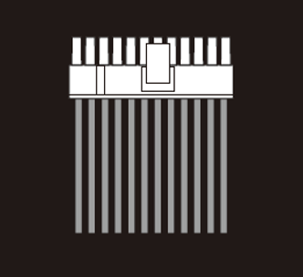 | 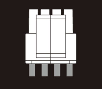 | 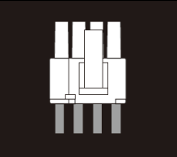 | 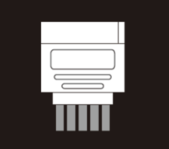 | 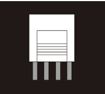 | 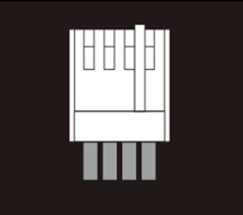 |
| Quantity | 1 | 1 | / | 2 | 1 | / |
| Cable Length (mm) | 0 | 450 | / | 400 | 200 | / |
ENVIRONMENT
Operation and storage conditions.
Operation
Operating temperature from -10℃to 70℃. Maximum output power falls off linearly as operating temperature increases from 40℃.
Shipping and Storage
Shipping and storage temperature from -40℃ to 80℃. Relative humidity to 95% non-condensing.
Altitude
Operating 10,000FT max. Storage 50,000FT max.
SAFETY & EMC
Specified certificates will be applied upon customers’ requirements.
Safety Standards
The design meets RoHS Directive (2011/65/3u) and EU (2015/863).
EMC Emission
The design meets Electromagnetic Compatibility Directive (2014/30/EU).
OTHERS
MTBF, dimension, weight and package content.
MTBF
The demonstrated MTBF (mean time between failures) shall be 100,000 hours of continuous operation at 25℃ of full load at normal DC input. The MTBF of the power supply shall be calculated in accordance with MIL-HDBK-217F.
Dimension
56mm (L) x 34mm (W) x 16mm (H), including 24pin connector.
Weight
80 grams excluding cables. 120 grams including cables.
Package Content
One PSU, one cable kit with 5pin connector connecting to PSU.
CONTACT
Pico Box headquarters locates at Shenzhen and can be contated by Email.
- Company: Pico Box Technology Limited
- Address: 901 Bldg. 3, Yesun Intelligent Community II, Guanlan, Longhua, Shenzhen 518000, China
- Email: oversea@pico-box.com
- Website: www.pico-box.com